I would like to use a nice controller on my Wii for those more complex games, but a Classic Controller is still expensive.
As there are some old controllers around the house why not trying to use them through an Arduino?
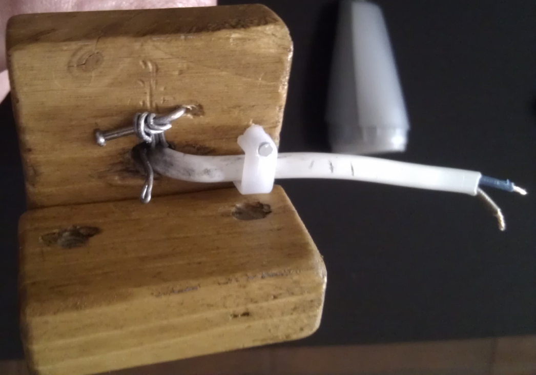
Wiimote has a proprietary connector, so it's better to use the cable from a broken or fake controller extension (like nunchuck). I bought one from ebay for about $3. It's wires are very thin and hard to solder, but I'm hoping they will suffice.
I opened the connector to try to replace the wires for thicker ones, but they are well stuck inside the connector, so I decided not to risk breaking it.
There is a lot of documentation on how to hack most of the capabilities of this controller (and they are a lot!), but even then it can be frustrating to a newbie like me to get it working.
I found a cool sample on http://gitorious.org/randomstuff/arduino-wiimote but it was outdated I wouldn't compile on Arduino 1.0 IDE.
So I did some modifications that I keep in my own repo (all my documentation is on the code).
As a test I used the Genesis controller I wrote about in the previous post.
The code for using both in the same Arduino is in this branch.
All I've done for now was a very crude attempt to prove functionality.
Next I'm thinking of a more permanent solution with power saving in mind. Also I would like to use other kinds of controller.
Sunday, January 27, 2013
Genesis controller on Arduino
I found an old Genesis controller on a flea market and I though of reusing it for future projects.
Its pinout is well documented (pinout) and it's easy to use with an Arduino.
Here's my GitHub stored simple example on how to communicate with it (with documentation):
Sample Code
Its pinout is well documented (pinout) and it's easy to use with an Arduino.
Here's my GitHub stored simple example on how to communicate with it (with documentation):
Sample Code
Thursday, July 12, 2012
Project: NiteLite (step 1)
So, finally something about this project!
The idea has been slightly changed since I installed a LED tape on my kitchen counter, but there are other places in the house where to use this project.
In order to start slow and getting things done, I decided to build an Arduino prototype first. Then I'll try bit by bit to alter the configuration to avoid using an IC (if possible).
This project is the use of a motion sensor and an LDR to light up some LEDs when I pass by the sensors at night.
I already wrote about the PIR Motion Sensor and the LDR on previous posts.
Now it's time to use them together.
The PIR Motion Sensor needs 6 to 12V to work correctly because it has an in-built 5V regulator. As I intend to use it with an Arduino or with an external regulator for the whole circuit, I decided to bypass that internal regulator.
I read on Sparkfun's forums that some people had no problems from doing that simple bypass, and it looks safe enough, so I managed to it with some clumsy soldering:
I connected the sensors like on the previous posts and added a couple of pots to control LDR sensitivity and on time for the LED. Looks a mess, but it's quite simple.
Here are the schematics for a better understanding:
And of course, all this needs some Arduino code:
void setup() {
pinMode(2, INPUT);
pinMode(5, OUTPUT);
Serial.begin(9600);
}
//int sample = 0;
void loop() {
// LDR value: the bigger the value, the darker the room
// mapping the LDR input to correspond to a valid PWM value
int m = map(analogRead(A1), 0, 1023, 0, 255);
// PIR value: when motion is detected turns LOW, else HIGH
int v = digitalRead(2);
// Sensitivity pot
int p = map(analogRead(A0), 0, 1023, 0, 255);
// Time pot
int t = map(analogRead(A2), 0, 1023, 1000, 10000);
if( m > p && v == LOW )
{
digitalWrite(5, HIGH);
delay(t);
}
else
digitalWrite(5, LOW);
// Writes to serial only 1 in 5 turns
/*if(sample % 5 == 0)
{
Serial.print("LDR: ");
Serial.print(m);
Serial.print(" Sense: ");
Serial.print(p);
Serial.print(" PIR: ");
Serial.print(v);
Serial.print(" Time: ");
Serial.println(t);
}*/
delay(50);
// Avoid overflow
/*if(sample == 10000)
sample = 0;
sample++;*/
}
Monday, July 9, 2012
LDR - Light sensor
For a coming project I'll need to know if a room has the lights on or off.
That's when a Light Dependent Resistor (LDR), or photocell comes in handy.
As usual, Ladyada provides an excellent tutorial on understanding and using electronics: Ladyada's 101 on LDR
I also found useful info here.
For the LDR that I have, I'm using this Datasheet. I'm not sure if this is the correct datasheet, but for this component I think it should be close enough.
The quantity of light can be measured in Lux, Lumen or Candela depending on several factors.
Here's some more info.
In this case, here's a table of some real world approximate Lux values, in order to understand the values we need to read:
Light source LUX
---------------------------
Moonlight 0.1
60W Bulb at 1m 50
1W Bulb at 0.1m 100
Fluorescent Lighting 500
Bright Sunlight 30,000
The resistance of a LDR can vary from +/-400 Ohm (for Bright Sunlight) to +/- 2 MOhm (in the Dark), depending also on the make of the component.
Here are some of the values I measured (from bright to dark):
Sunday, May 20, 2012
Bedflower
As I couldn't find a decent and cheap lamp to attach to my bed as a reading light, I decided to build one.
I saved some deodorant bottles as they have a nice shape and can be used in some projects.
I noticed that some light bulb screw bases I had fit perfectly in those bottles.
For the neck I used wire wrapped in a long screw for shape and strengthened it with more wire inside to have a flexible but strong neck.
As a base I chose make it out of wood so I tried to saw some squares that would connect with a 45º angle cut, but the nails I have are to big for that cut and the wood block chipped.
Then I drilled the blocks to pass the lamp's neck and some screws that will be used to secure the base to the bed.
After some polishing,
I nailed the pieces together and polished again:
These are the switches I applied to make the wires from the base to the wall wart:
Then I secured the neck to the base using the neck wire and a nail to fixate it, and secured the electrical wire as well.
I connected the switch so that it covers the holes where the screws go into, making it more aesthetic.
And here are the screws applied to the base.
So were almost there.
To make it more appealing I covered the neck of the lamp in a painters tape.
It looks kind of pretty in this photo, doesn't it? Sadly, that's the only case...
So here's the end result.
In the end, I don't think this is much appealing or practical as it is.
I made lots of mistakes on this that I was able to correct and others that I couldn't.
But the main idea is solid and when possible I will make a better version of this.
---------------------------------------------------------------------------------
Time to some improvements!
The wood panels were too small and would easily come out of the bed, so I switched to some bigger ones. But now they are too big to be plain.
I decided to try a little design:
With a X-Acto I cut on the wood some leaf design I found on Google and with my old soldering iron burned the wood to create the pattern you see above.
But I didn't feel it was enough. The upper part was still ugly.
So I tried another artistic approach:
I bought some disposable table spoons (used about 30 for testing and the final look) and glued them to a piece of toilet paper roll.
After two layers of glued spoons, I added other two layers of bent spoons and covered the hot glue at the base with some painters tape to hide the mess.
The final result is a beautiful (I think) flower:
What do you think?
Monday, January 23, 2012
Understanding Servo Motors
"Servo motors have three wires: power, ground, and signal. The power wire is typically red, and should be connected to the 5V pin on the Arduino board. The ground wire is typically black or brown and should be connected to a ground pin on the Arduino board. The signal pin is typically yellow, orange or white and should be connected to a digital pin on the Arduino board. Note servos draw considerable power, so if you need to drive more than one or two, you'll probably need to power them from a separate supply (i.e. not the +5V pin on your Arduino). Be sure to connect the grounds of the Arduino and external power supply together."
I bought my Servo motors from InMotion who imported them from SparkFun.
It's easy to control a Servo with Arduino using the libraries distributed with the Arduino IDE, but with only three wires, how is that controlled?
A servo motor expects a PWM signal with a very specific period and duty time.
Usually a 20ms period and a 1ms to 2ms as duty time.
On a regular servo the minimal duty cycle means a 0º position, the maximum corresponds to 180º and half way equals 90º.
On a full rotation servo, each period to motor rotates acording to the duty cycle.
Under 1,5ms rotates counter-clockwise and above 1,5ms rotates clockwise.
Controlling a servo from Arduino:
To test the theoretical knowledge I tried to run this simple sketch:
Worked fine!
But for the best control, why not use a tested and proven library?
So I used Arduino's IDE Sweep example that rotates the Servo from side to side (0 to 180 degrees and back) using a class designed for that purpose.
The Sweep example seems simple and self-explanatory for me to give more detail about it.
In my full rotation servo I noticed that it rotated more going counter-clockwise than when moving clockwise.
I don't know why does it happen...
I bought my Servo motors from InMotion who imported them from SparkFun.
It's easy to control a Servo with Arduino using the libraries distributed with the Arduino IDE, but with only three wires, how is that controlled?
A servo motor expects a PWM signal with a very specific period and duty time.
Usually a 20ms period and a 1ms to 2ms as duty time.
On a regular servo the minimal duty cycle means a 0º position, the maximum corresponds to 180º and half way equals 90º.
On a full rotation servo, each period to motor rotates acording to the duty cycle.
Under 1,5ms rotates counter-clockwise and above 1,5ms rotates clockwise.
Controlling a servo from Arduino:
To test the theoretical knowledge I tried to run this simple sketch:
void setup() {
// put your setup code here, to run once:
pinMode(9, OUTPUT);
}
void loop() {
// put your main code here, to run repeatedly:
digitalWrite(9, HIGH);
delay(2);
digitalWrite(9, LOW);
delay(18);
}
Worked fine!
But for the best control, why not use a tested and proven library?
So I used Arduino's IDE Sweep example that rotates the Servo from side to side (0 to 180 degrees and back) using a class designed for that purpose.
The Sweep example seems simple and self-explanatory for me to give more detail about it.
In my full rotation servo I noticed that it rotated more going counter-clockwise than when moving clockwise.
I don't know why does it happen...
Thursday, January 19, 2012
Nokia 5110 LCD
I bought a SparkFun Nokia 5110 LCD through InMotion. Both sites have the datasheet and example documentation for how to use it.
Adafruit also sells this and documents its use with another excellent Ladyada tutorial.
Here it is with connectors already soldered:
The soldering is pretty bad. Maybe I should buy a new tip for my soldering iron...
This screen supports direct connection to an Arduino (5V), but in doing so we push it to the datasheet defined limits, so to it is best to reduce all signals to a confortable 3.3V.
My Arduino Duomilanove only outputs 5V signals, so in order to translate those signals to 3.3V, the simplest way is to use a Voltage Divider.
I used this site to calculate the best resistor values to use for this case (10kOhm and ~5kOhm).
Adafruit offers a free level shifter with the LCD that can be used as a more efficient Voltage Divider.
Also to light up the 4 leds used as backlight I used a 22Ohm resistor, so that I could connect to a 5V signal on the Arduino in order to control them with PWM.
And here it is using the Arduino example code 2:
Adafruit also sells this and documents its use with another excellent Ladyada tutorial.
Here it is with connectors already soldered:
![]() | ![]() |
The soldering is pretty bad. Maybe I should buy a new tip for my soldering iron...
This screen supports direct connection to an Arduino (5V), but in doing so we push it to the datasheet defined limits, so to it is best to reduce all signals to a confortable 3.3V.
My Arduino Duomilanove only outputs 5V signals, so in order to translate those signals to 3.3V, the simplest way is to use a Voltage Divider.
I used this site to calculate the best resistor values to use for this case (10kOhm and ~5kOhm).
Adafruit offers a free level shifter with the LCD that can be used as a more efficient Voltage Divider.
Also to light up the 4 leds used as backlight I used a 22Ohm resistor, so that I could connect to a 5V signal on the Arduino in order to control them with PWM.
![]() | ![]() |
And here it is using the Arduino example code 2:
![]() | ![]() |
Wednesday, January 18, 2012
Electronics Stores
Here are my favorite electronics stores:
Portuguese:
Aquario (Porto) - Nice collection of generic electric components, ICs and tools, but not for hobbyist electronics, like sensors, motors or other robotics components;
InMotion (On-line) - Nice catalog with products from SparkFun and Pololu, etc. Usually they offer the shipping costs at Christmas. It is possible to order SparkFun items by mail that aren't on their catalog.
PTRobotics (On-line) - Like InMotion, they have a very good catalog of products.
Found a link on a forum with their own list: LusoRobotica
Worldwide:
Sparkfun (US) - Best generic store, but the shipping costs can be very high for a direct order. The most common items can be found in distributors around the world.
Adafruit (US) - Main competitor for SparkFun. Can't tell wich is best.
Pololu (US) - Best store for motors and related products, shipping costs have the same problem as SparkFun;
eBay stores (mostly China) - Sometimes we can find great deals with free shipping from high trust rated sellers.
Friday, January 13, 2012
Electronics Components
Here I'll be updating some links about electronics components, as a wiki with the best information I can find.
- Zener Diodes
- Zener Diodes
Thursday, November 24, 2011
Taking a peek at Android source code (decompiling)
Are you curious about some Android apps behavior?
Do you want to learn how some things are done on Android?
Android apps are written in Java, so it's easy to assume that a .apk file is the same as a .jar file. And if you know a bit of the Java world, you know that a .jar file is nothing more than a renamed .zip file containing compile binaries (.java files).
In the case of .apk files you can find a single classes.dex file (if the app is optimized, you'll find an .odex file) for code and resources and manifest related files. These files are generally not directly accessible. For reading them you'll need some tools.
For some info about the difference between .dex and .odex files you can go here. I won't talk about odexing apps in this article.
Remember that when decompiling an app you won't get the exact original source code, but an approximate that may not even compile back.
Here are the tools for you to open an .apk file:
- dex2jar;
- JD-GUI (Java Decompiler);
- apktool;
You can obtain two different results depending on the tools you use. With dex2jar you can convert a classes.dex file to a regular .jar which can be decompiled by Java Decompiler.
With apktool you can obtain the AndroidManifest.xml, all resource files and the code in a kind of assembler language.
Both of the tools are easy to use:
dex2jar (windows) --> dex2jar.batclasses.dex
apktool (windows) --> apktool.bat d.apk
Now to the hard part. Go play!
Do you want to learn how some things are done on Android?
Android apps are written in Java, so it's easy to assume that a .apk file is the same as a .jar file. And if you know a bit of the Java world, you know that a .jar file is nothing more than a renamed .zip file containing compile binaries (.java files).
In the case of .apk files you can find a single classes.dex file (if the app is optimized, you'll find an .odex file) for code and resources and manifest related files. These files are generally not directly accessible. For reading them you'll need some tools.
For some info about the difference between .dex and .odex files you can go here. I won't talk about odexing apps in this article.
Remember that when decompiling an app you won't get the exact original source code, but an approximate that may not even compile back.
Here are the tools for you to open an .apk file:
- dex2jar;
- JD-GUI (Java Decompiler);
- apktool;
You can obtain two different results depending on the tools you use. With dex2jar you can convert a classes.dex file to a regular .jar which can be decompiled by Java Decompiler.
With apktool you can obtain the AndroidManifest.xml, all resource files and the code in a kind of assembler language.
Both of the tools are easy to use:
dex2jar (windows) --> dex2jar.bat
apktool (windows) --> apktool.bat d
Now to the hard part. Go play!
Thursday, November 17, 2011
First Hack - The LED Strip
Finally finished my first hack.
I needed a light for my kitchen counter, so I ordered a LED Strip from eBay and hacked an AC adapter to include an ON / OFF button and to connect it to mains without using a power socket.
So here's the theoretical work:
To cover the surface of my counter I used 48 segments of the LED strip (about 2 meters). Each segment has 3 white SMD leds (type 3528) and a 150 Ohm resistor. For it to work it needs a 12V power source with sufficient current output.
After learning from [ladyada] about these strips I figured that the theoretical current each segment needs to function at it's maximum is 16 mA. That is:
12V total - (3 leds * 3.2V) / 150R = 0.016A
For the total 48 segments that's 768 mA, resulting in under 10W lighting!!!
For that I bought a SMPS AC adapter in order to guarantee the regulated 12V while using that much current. An average (unregulated) AC adapter wouldn't provide nor the 12V neither near the maximum 1A stated. [ladyada] also shed me some lights on that matter.
For the practical work:
As you will see for yourself, the tools weren't exactly the best suited for the job: a kitchen knife to cut, a soldering iron to remove plastic, a hammer and a nail to open holes...
In order to cut the space for the switch button in the AC adapter, my kitchen knife wasn't enough, so I used my soldering iron to heat a metal needle and a kind of a thick clip used by stores to keep shirts folded in it's package. Even so it was a hard work.
Then I just needed to solder the switch button and the wire to the board and cover it all with electrical tape.
And there we have it!
Our working LED Strip!
I needed a light for my kitchen counter, so I ordered a LED Strip from eBay and hacked an AC adapter to include an ON / OFF button and to connect it to mains without using a power socket.
So here's the theoretical work:
To cover the surface of my counter I used 48 segments of the LED strip (about 2 meters). Each segment has 3 white SMD leds (type 3528) and a 150 Ohm resistor. For it to work it needs a 12V power source with sufficient current output.
After learning from [ladyada] about these strips I figured that the theoretical current each segment needs to function at it's maximum is 16 mA. That is:
12V total - (3 leds * 3.2V) / 150R = 0.016A
For the total 48 segments that's 768 mA, resulting in under 10W lighting!!!
For that I bought a SMPS AC adapter in order to guarantee the regulated 12V while using that much current. An average (unregulated) AC adapter wouldn't provide nor the 12V neither near the maximum 1A stated. [ladyada] also shed me some lights on that matter.
![]() | ![]() | ![]() |
| White LED Strip | Suitable AC Adapter | The best switch button I could find |
For the practical work:
As you will see for yourself, the tools weren't exactly the best suited for the job: a kitchen knife to cut, a soldering iron to remove plastic, a hammer and a nail to open holes...
![]() | ![]() | ![]() |
| The innards of a power outlet | Mains power derivation | Adhesive cable duct |
In order to cut the space for the switch button in the AC adapter, my kitchen knife wasn't enough, so I used my soldering iron to heat a metal needle and a kind of a thick clip used by stores to keep shirts folded in it's package. Even so it was a hard work.
![]() | ![]() | ![]() |
| Pierced top cover from the AC Adapter | Creating the space for the switch button | The working conditions |
Then I just needed to solder the switch button and the wire to the board and cover it all with electrical tape.
![]() | ![]() | ![]() |
| The final cut | Connecting the switch button | That's a wrap |
And there we have it!
Our working LED Strip!
![]() | ![]() |
Subscribe to:
Posts (Atom)


